
I did a thing: hacking an old garage door opener
Way back in semester 1 of 2017, I did a (computer) security engineering course. Not because I was particularly interested in security, but because I thought it would be a fun way to pad out the rest of my computer science degree, and I was after a relatively easy course - I was doing my thesis that semester as well.
As part of the course assessments, we were asked to formulate a security-related technical challenge for ourselves, complete it before the end of semester and document it throughout. I ended up doing something I’ve always wanted to do: opening my garage door (without using its actual remote) by reverse engineering it.
The following blog post is basically all the blog posts I wrote documenting the project rolled into one. I wanted to give it a better home than the awful MOOC website it currently lives on, so now it’s here too.
Part 1: Getting to know the opener
This is my garage door opener:
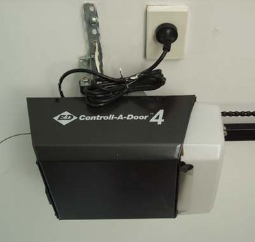
It was installed way back in 2001, so it’s a pretty old model. It’s controlled by this remote:
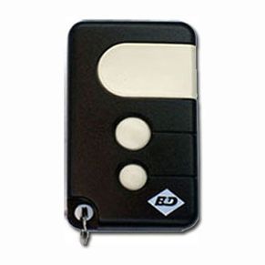
Now, since I was born sometime in the last century, I knew that the remote used radio waves to communicate with the opener. This meant that to reverse engineer the opener, I’d have to tune into the remote’s frequency and figure out what gets sent to the opener.
First, to find the frequency. I read my garage door opener’s instruction manual to try and figure out which frequency it was transmitting on, since I can’t really sit there all day going through millions of frequencies. The manual said 433MHz. Apparently this is a pretty common frequency for this kind of application.
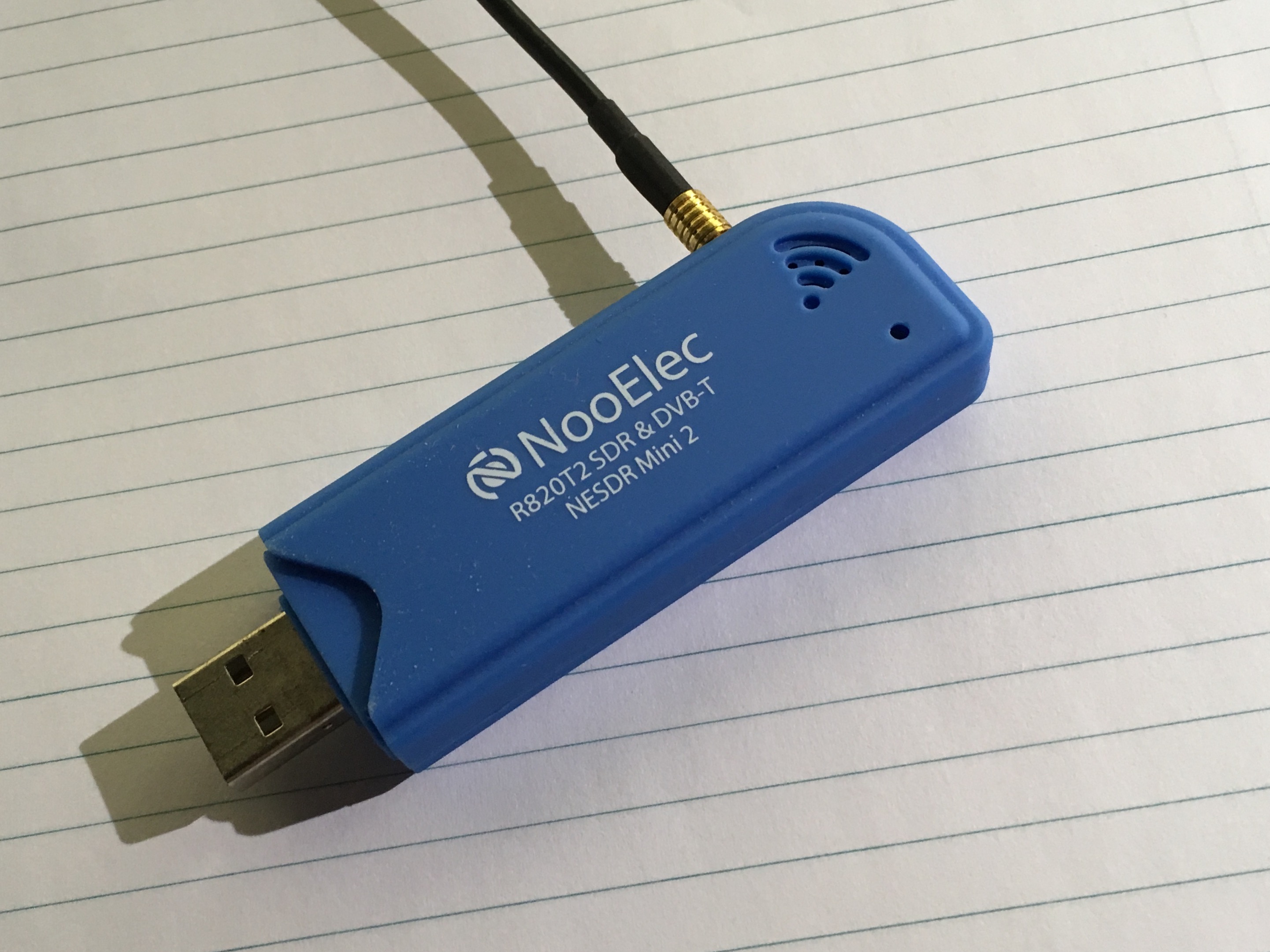
So I get my Ol’ Faithful RTL-SDR dongle out. (It’s called that because I’ve never used it for anything productive except listening to JJJ every once in a while, but it still works…) It’s just a USB dongle with a basic antenna attached to it.
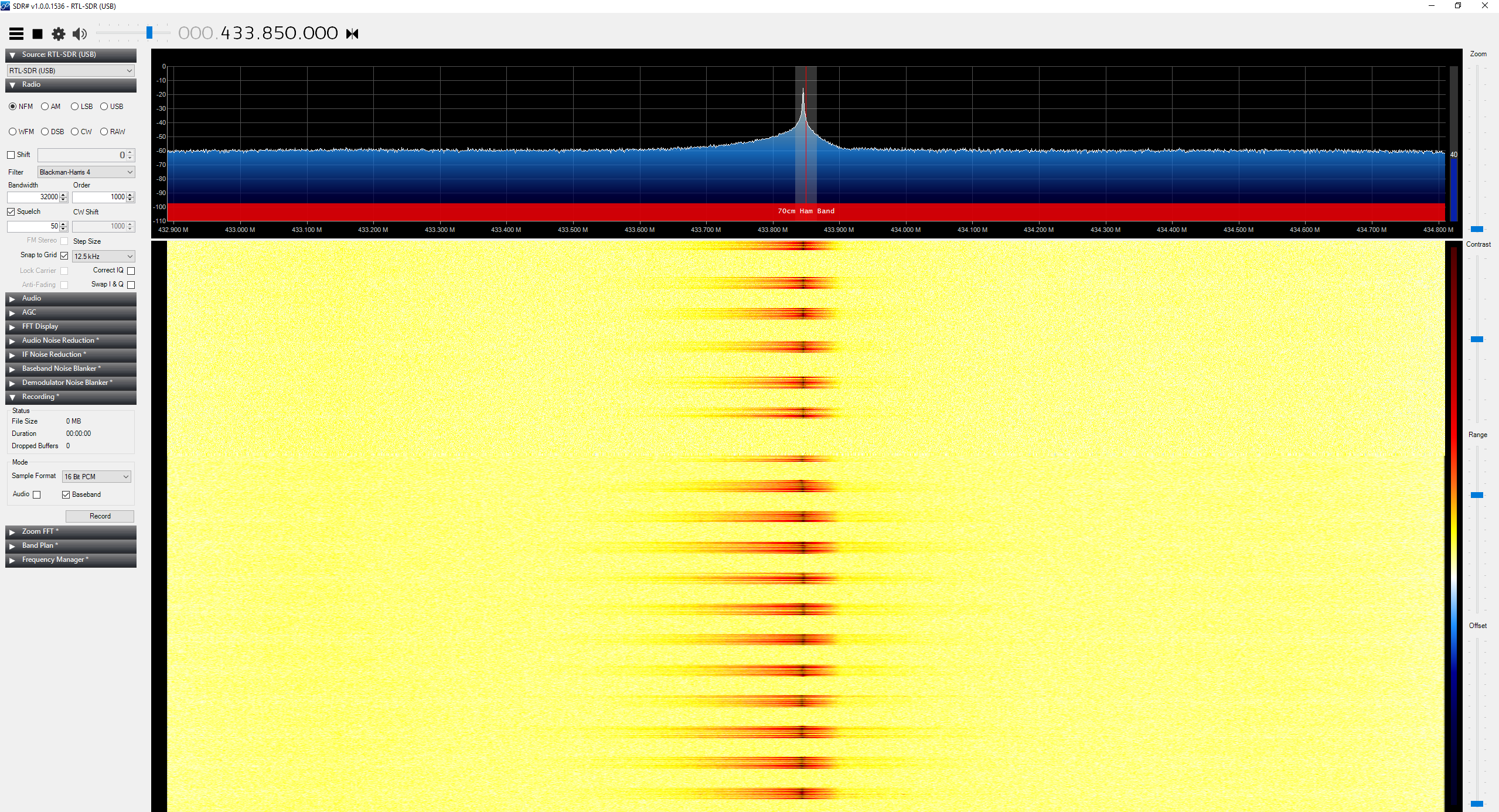
I load up SDR#, which is an application that allows me to use the dongle to listen on the airwaves and visualise what’s going on. Here’s me listening to JJJ (it’s a bit noisy):
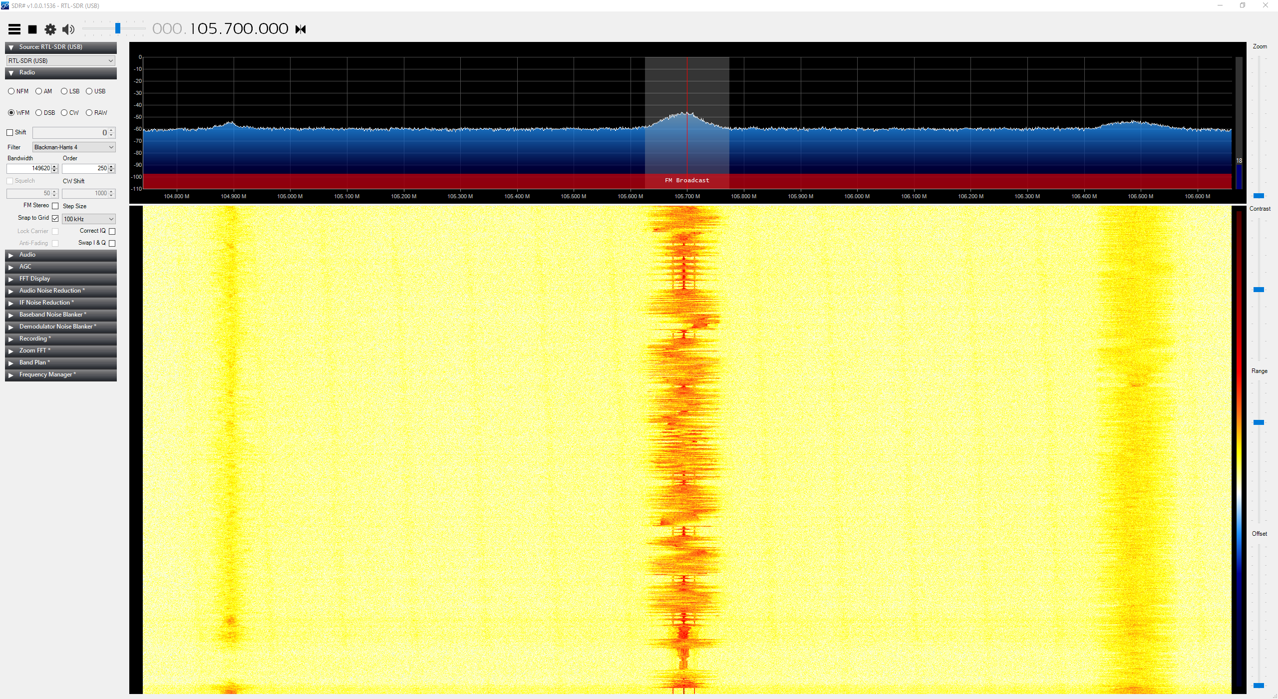
Enough about me listening to the radio though. I tune it to 433MHz and press my garage door opener remote a few times… voila!
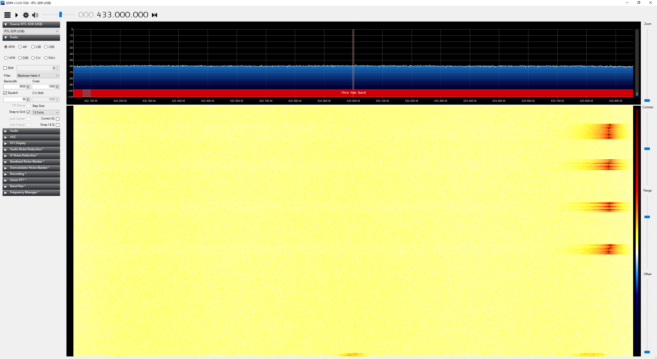
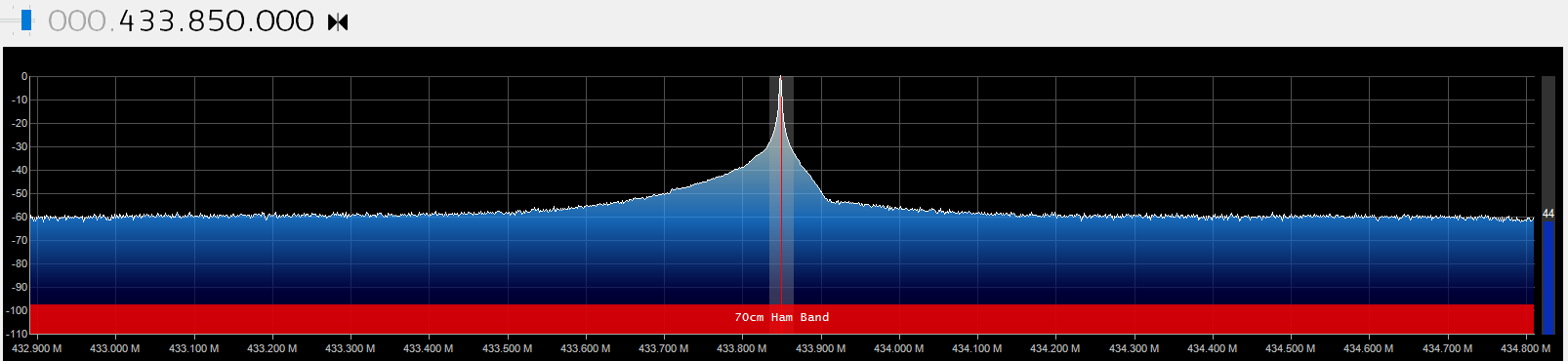
It looks to be closer to 433.875MHz so I tune it closer:

I’ve hit paydirt! It’s a very well-defined signal that peaks in the vicinity of 433.875MHz (a little off, but I don’t get that much resolution when tuning the RTL-SDR).
I made an audio recording of it:
It’s a bit noisy, so my next step is to clean it up a bit and have a good long look at the signal in an audio editing application to see if I can make out the code being transmitted.
Part 2: Audio analysis
I attempted to reduce the noise in my recording of the remote signal by using Audacity’s noise reduction effect. Unfortunately, it didn’t help much as it reduced the amplitude of the signal too.
At this point I decided to try other things. I did some reading on noise reduction for RTL-SDR tuners, and found some very promising advice to use a ferrite core on the antenna cable, but unfortunately I couldn’t find a ferrite core anywhere at home. It’s frustrating because I KNOW I have one lying around!
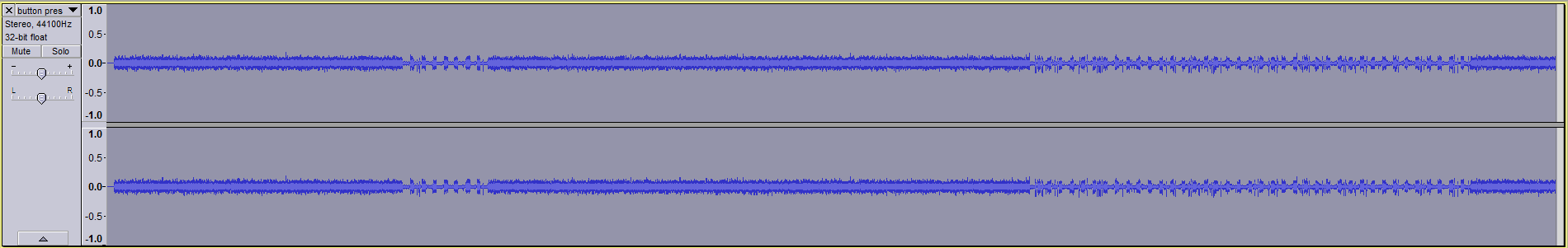
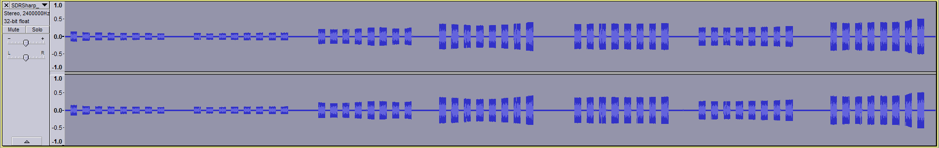
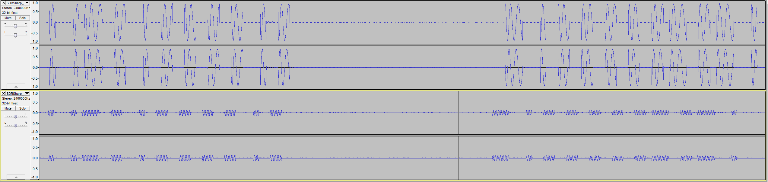
It was time to get creative. Using a different USB port on my computer seemed to improve the signal somewhat, but what did it was holding my hand around the antenna. I’m not sure how it works, but I imagine it concentrates the signal. The result was a practically noiseless recording with a very distinct signal to use for analysis.
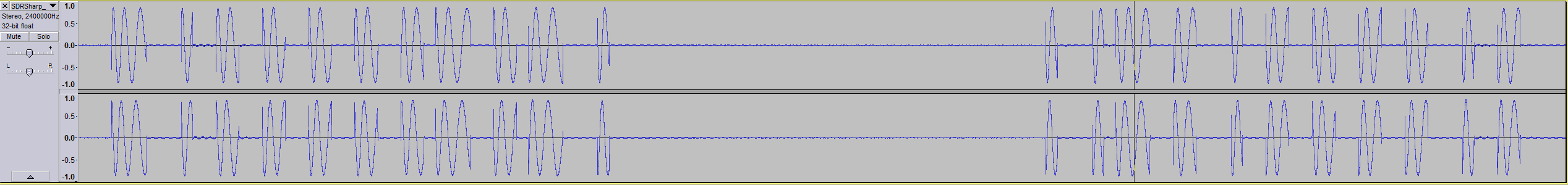
Pictured is the signal when I held the button down for 5.5s.
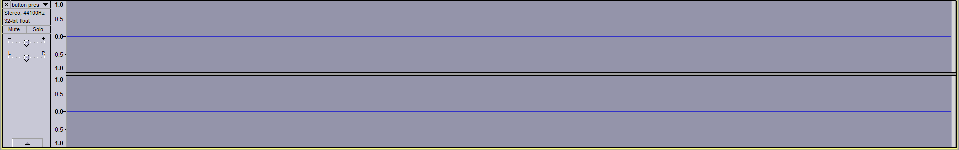
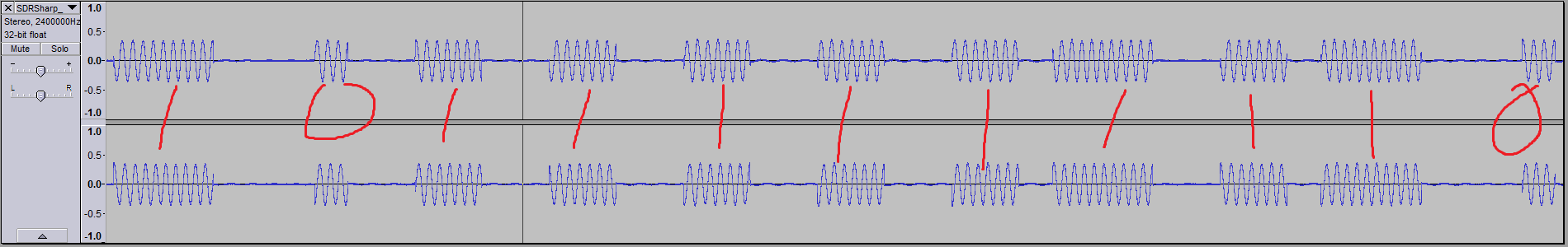
Next I wanted to see whether I could discern individual bits in the signal. In Audacity, I selected a sequence of packets 0.582s in length. I noticed there were 8 packets in each press.
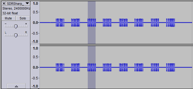
Diving down into each packet, I found there were 2 distinct sequences, each repeated 4 times (you can see the pattern if you squint at the above picture hard enough):

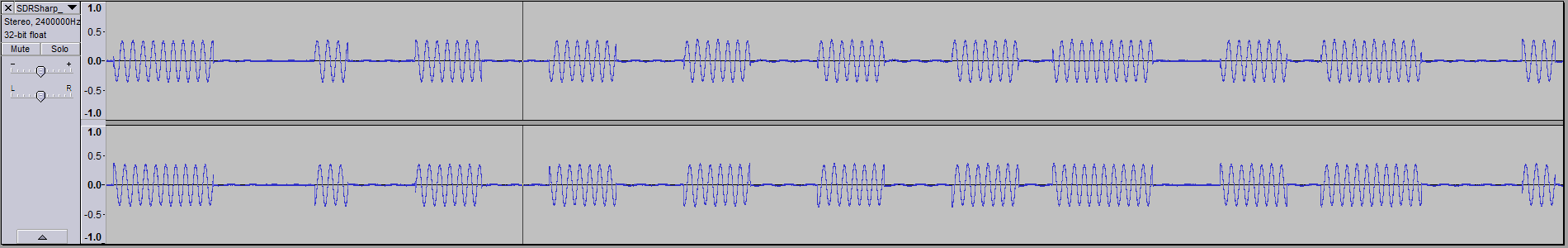
This was clearly something in binary as there are only 2 different signal states (on and off). If this was binary information, then I would need to figure out what modulation was used. I went back through some old lecture slides from TELE3113 (which dealt extensively with modulation); lo and behold, on the 3rd slide from a lecture on digital bandpass modulation, we had this:
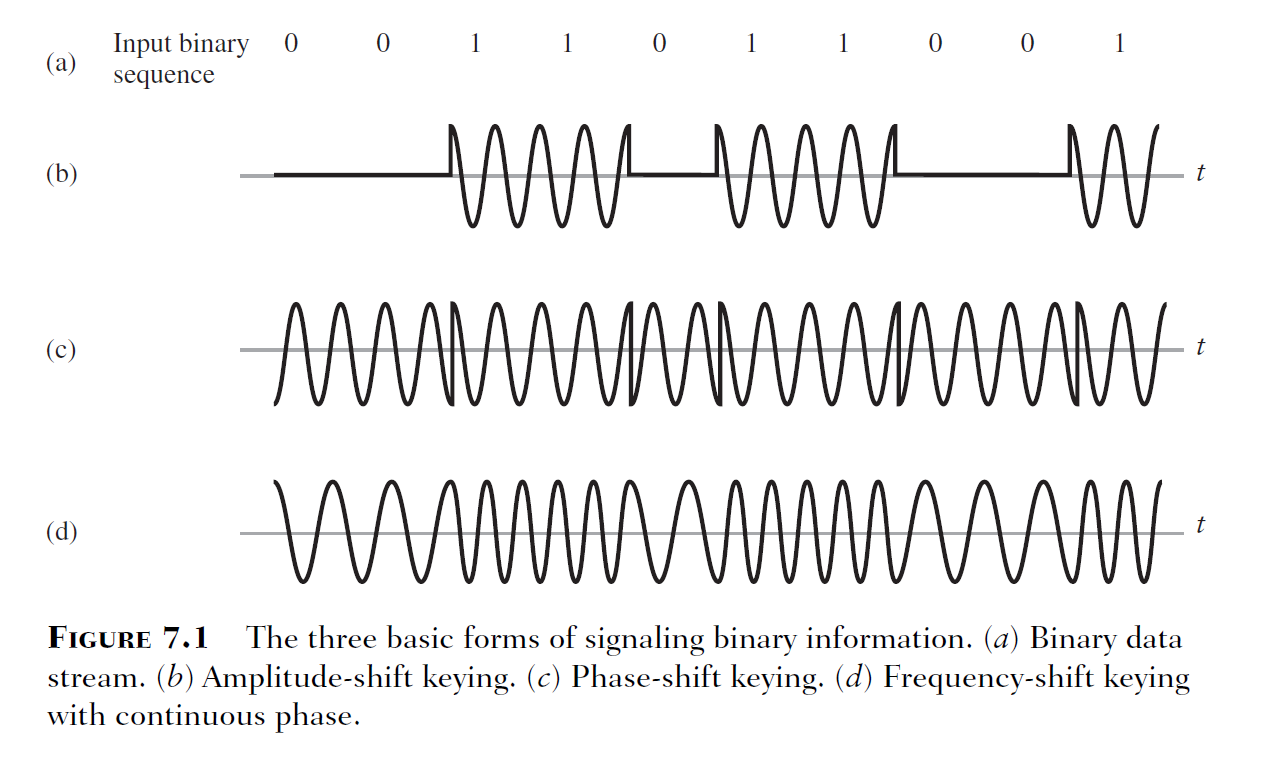
What I think I was seeing in Audacity was amplitude-shift keying (ASK). It’s particularly pronounced in the waveform as the sine wave appears to be cut off abruptly in the transitions between 0 and 1. Looking at the waveform, it appears the period of each bit was 1ms (measuring the period of each solitary 1).
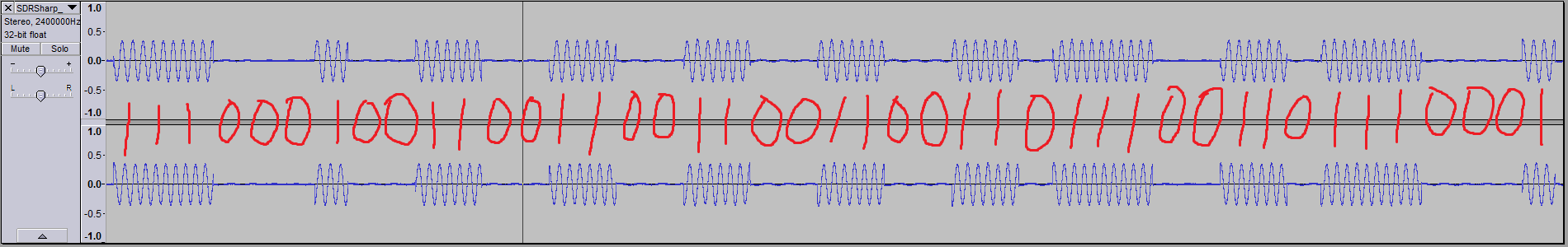
So now to decode it into binary. I used Audacity to carefully select each sequence of bits to find the duration, and from there extrapolated how many bits were in the sequence (or stream).
From this, I get:
10001011100110001001100110011001100010011 (41 bits?)
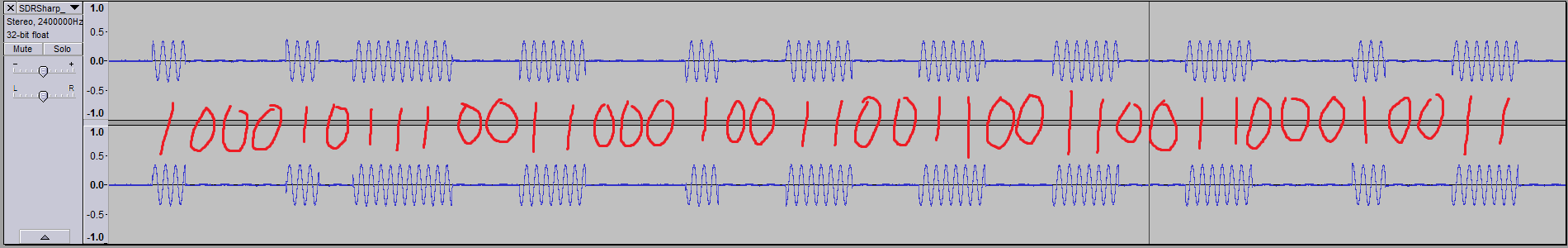
1110001001100110011001100110111001101110001 (43 bits?)
I was a bit put off by this, because who lumps 41 bits into a stream? That’s 5 bytes and a bit! My experience tells me that they’re usually nice round numbers. I needed to verify this somehow, as I couldn’t determine where the start and end points of the packets were – for all I knew, there were a couple of zeros in the beginning of packet 1, or that the radio silence between the packets were all zeros. I did notice that 11001100110011000 occurs twice in both streams, but that was it.
At this point I got a bit stuck, and decided to do some research.
Part 3: Bit-squinting
A bit of Googling came up with this blog post.
In it, the author uses rtl_433 to decode a raw bitstream from various devices. While rtl_433 doesn’t have a preset for a garage door opener, I thought it would be perfect nonetheless because I wasn’t aware of any other program that did the same thing.
I fired up a Debian VM and fruitlessly tried getting my RTL-SDR dongle connected to it. No luck. In the end, I was able to find a Windows binary for rtl_433 that a kind soul made available to the world here.
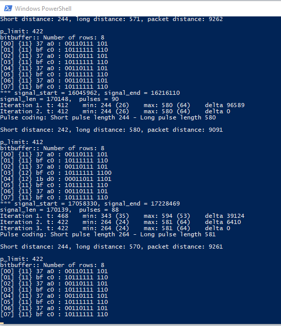
Using that, I could finally see the raw bitstream from my remote. Happy days!
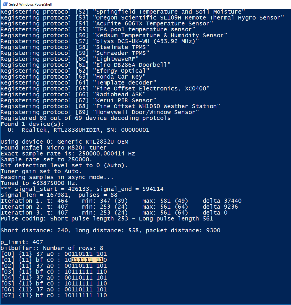
bitbuffer:: Number of rows: 8

[00] {11} 37 a0 : 00110111 101

[01] {11} bf c0 : 10111111 110

[02] {11} 37 a0 : 00110111 101

[03] {11} bf c0 : 10111111 110

[04] {11} 37 a0 : 00110111 101

[05] {11} bf c0 : 10111111 110

[06] {11} 37 a0 : 00110111 101

[07] {11} bf c0 : 10111111 110
It’s a nice round 10 bytes! But wait a minute. This is totally different from what I expected. I kept pressing the button, and rarely, I’ll get a different sequence altogether:
bitbuffer:: Number of rows: 8

[00] {10} bf c0 : 10111111 11

[01] {10} fd 40 : 11111101 01

[02] {10} bf c0 : 10111111 11

[03] {10} fd 40 : 11111101 01

[04] {10} bf c0 : 10111111 11

[05] {10} fd 40 : 11111101 01

[06] {10} bf c0 : 10111111 11

[07] {10} fd 40 : 11111101 01
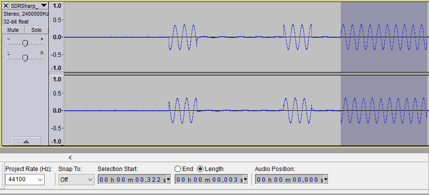
I went back to look at the waveforms to see if I could reconcile what I was seeing with what rtl_433 returned. If I interpreted long pulses as 1s and short pulses as 0s, then they would match the results from rtl_433:
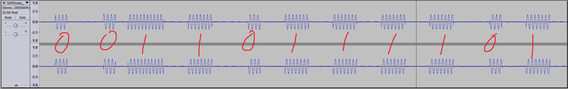
So how was the signal encoded? It seems that it’s using on-off keying (OOK), which is a form of ASK, alongside pulse width modulation (PWM). I’ve never heard of OOK/PWM used in tandem, but apparently this is quite common with keyfobs such as my opener remote – Google brought up this LabVIEW experiment decoding the signal transmitted from a keyfob operating on 315MHz, as well as a blog post on hacking similar 433MHz devices using this encoding.
From all of this bit-squinting, I learnt that the wireless security on my garage door opener is a sack of crap! (Excuse my French.) The signal transmitted does not (or rarely) changes, so all an attacker needs to do is listen in on the transmission from my remote, analyse it like I’ve done here, and simply replay it while in range of the garage.
Part 4: The fun part
I went out to my local electronics store (Altronics) and bought an RF transmitter module with an operating frequency in the region of 433MHz. Taking a look at the datasheet, it does ASK modulation and has a wide input voltage range (no need to level shift!)
Here’s the relevant bit of the datasheet:
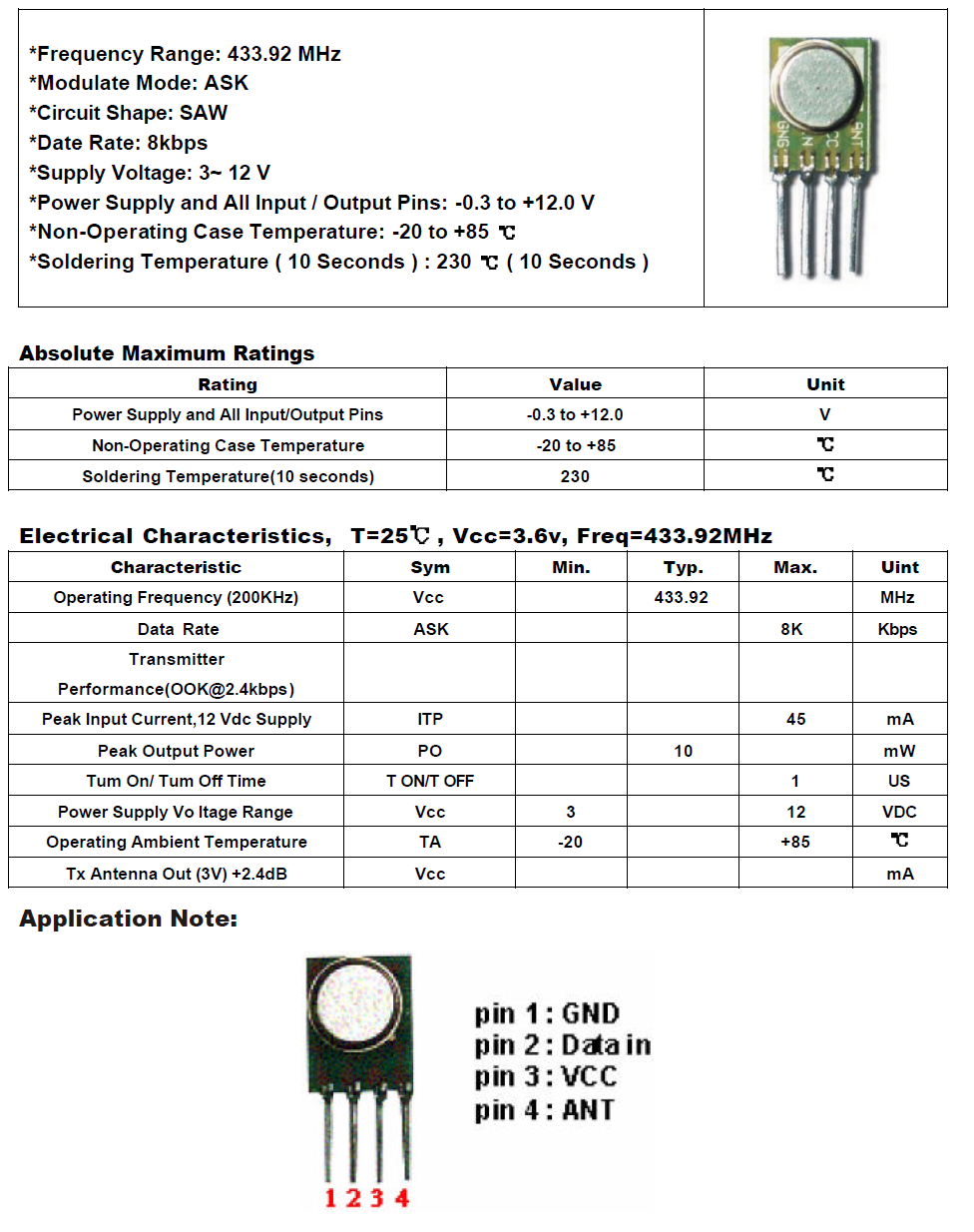
You’ll remember that I found my remote to be transmitting in the vicinity of 433.875MHz, but this module only transmits at 433.92MHz, which was a worry since I didn’t know how sensitive my garage door opener would be. I was even more worried when I got to the part that says CIRCUIT SHAPE: SAW. What?
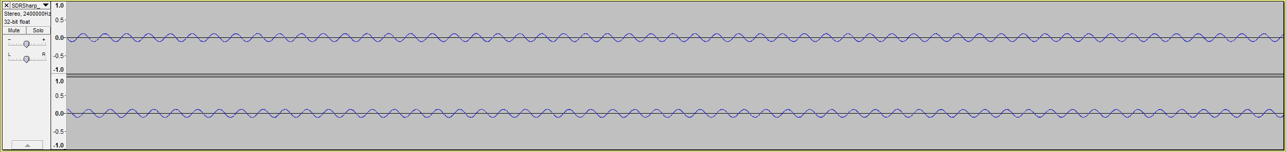
I decided to have a look at what it was outputting. I loaded up SDR# and wrote a short and sweet sketch in Arduino to output HIGH to the pin attached to the module’s data pin periodically. Here’s what I saw:
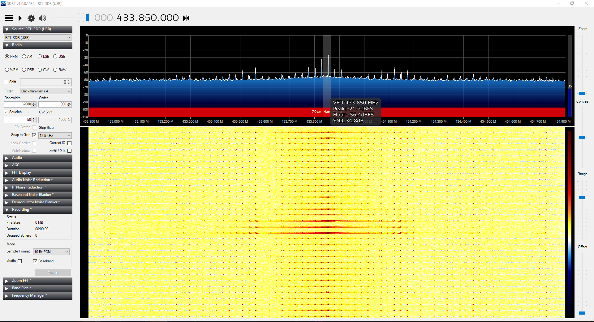
As far as I know, plain Jane sine waves don’t have harmonics like that, and I wanted a sine wave to replicate the signal from my remote as closely as possible. I made a baseband recording just to be sure:
I had no freaking idea what I was looking at, so in an act of desperation I put a basic RC low pass filter on it to try and coax it into a more familiar waveform. I used this calculator to come up with the component values, given a cutoff frequency as close as possible to 433.875MHz.
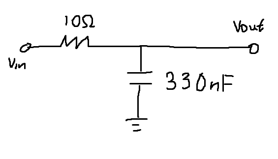
With the RC circuit in place on the ANT (antenna) output of the module, I made another recording:
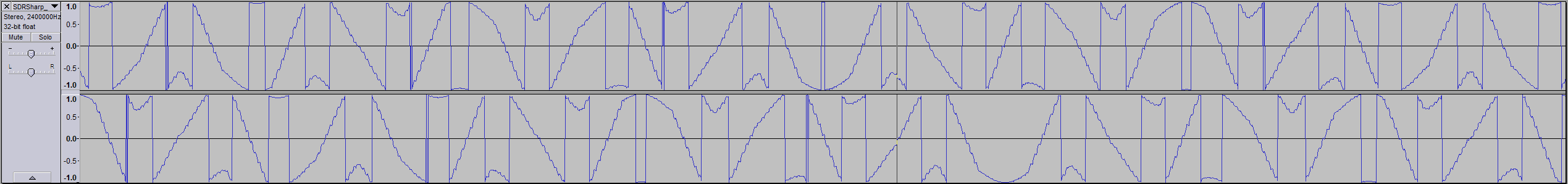
I overcooked the cutoff frequency a little but it’s a lot closer now at around 433.85MHz. In Audacity…
Much better!
So now I needed to get my Arduino to write the correct bits, with the correct timings, to the transmitter data input.
I needed 00110111101 and 10111111110, with 0 being transmitted as a short bit and 1 as a slightly longer bit. However the Arduino outputs 0 as 0 volts and 1 as 5 volts. What to do?
Thankfully it didn’t take me too long to figure it out. I could simply use the analysis I did earlier, where I thought the modulation used was simple ASK and painstakingly split the sequences into millisecond increments. Using that, I could get the timing as close to correct as I possibly can. Using Audacity, I also found that the dead air gap between the first and second bit sequences was 36ms, and between the second sequence and the next cycle of the first bit sequence to be 38ms.
Here’s the super simple sketch with all this information packed into it:
#include <SPI.h>

int outputPin = 12;
int buttonPin = 2;
int buttonState = 0;

int sequence1[41] = { 1,0,0,0,1,0,1,1,1,0,0,1,1,0,0,0,1,0,0,1,1,0,0,1,1,0,0,1,1,0,0,1,1,0,0,0,1,0,0,1,1 };
int sequence2[43] = { 1,1,1,0,0,0,1,0,0,1,1,0,0,1,1,0,0,1,1,0,0,1,1,0,0,1,1,0,1,1,1,0,0,1,1,0,1,1,1,0,0,0,1 };

void setup() {
  pinMode(outputPin, OUTPUT);
  pinMode(buttonPin, INPUT);
  Serial.begin(9600);
}

void loop() {
  buttonState = digitalRead(buttonPin);

  if (buttonState == LOW) {
    for (int j = 0; j < 4; j++) {
      Serial.print("begin sequence 1\n");
      int data;
      for (int i = 0; i < 41; i++) {
        data = sequence1[i];
        digitalWrite(outputPin, data);
        delay(1);
      }
      digitalWrite(outputPin, LOW);
      delay(36);
      Serial.print("begin sequence 2\n");
      int data2;
      for (int i = 0; i < 43; i++) {
        data2 = sequence2[i];
        digitalWrite(outputPin, data2);
        delay(1);
      }
      digitalWrite(outputPin, LOW);
      delay(38);
    }
    digitalWrite(outputPin, LOW);
    delay(1000);
  }
}
Quick explanation of what it’s doing (if you’re not interested you can skip this bit):
Digital pin 12 is used to output data to the transmitter. Pin 2 is used to input the button state. The way I’ve set up the button on the breadboard is with a pull-up resistor (so it reads HIGH, or 5V, when the button isn’t pushed and LOW, or 0V when the button is pushed and completes the circuit, thus pulling the pin to ground).
In the loop function, the conditional will check whether the button has been pressed (i.e. LOW). Inside the conditional, we have a loop that repeats its inside loops 4 times (remember that the bit sequences occurred in pairs 4 times). The inside loops simply loop through the array, outputting what’s in the array for a millisecond then moving on to the next bit until it gets to the end. Then there’s a dead air section of the required length where 0 is written to the pin.
Here’s the transmission in Audacity:
To check that it’ll be interpreted correctly, I go back to rtl_433:
That second transmission looks a little odd but it’s probably due to noise or interference. Otherwise, looking good!
Comparing the signal from the remote with the signal from my Uno:
The timing is a little off, but at this point I was hoping that the opener had a little tolerance toward these things.
In SDR#:
And here’s a video of it in action: